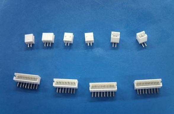
What is the name of the connector model?
The model naming of the connector, the model naming of the connector is the basis for customer procurement and the manufacturer’s organization of production. In the connector industry at home and abroad, there are two ways of naming product models: one is to use letter codes and numbers, and strive to The main structural characteristics of the product are reflected in the model name. The advantage of this method is that it is easy to identify, but the arrangement is too long and too complicated. With the miniaturization of the connector, it brings many difficulties to printing. At present, the connector is still popular in China. This method is stipulated in certain industry standards and even national standards, such as (printed circuit connector), (rectangular connector), (ribbon cable connector), (ribbon cable connector), etc., due to the connection The structure of the device is becoming more and more diversified. In practice, it is more and more difficult to cover a certain type of connector with a naming rule. Another idea is to use Arabic numerals. The advantage of this method is simplicity, easy computer management and small size. Logo printing of component products.

Electrical failure: The connection problem between the cable and the terminal of the enhanced new crimping technology is one of the main reasons for the warranty and connector system failures. For the automotive wiring system, crimping is a very common method for connecting the terminals For cables, this process has been proven reliable. Compared with soldering, it is more economical and easy to operate in terms of improving crimping reliability. In order to improve the geometry of the terminal clamp connector, connector manufacturers have invested A lot of energy, through an extensive analysis and experimental research, FCI not only developed a new type of analysis tool for crimping optimization, but also proposed a new type of crimping geometry with innovative significance.
FCI's "two-step" crimping solution proposes a crimping method that can be produced on a traditional crimping press with a typical high-speed crimping rate. When the "two-step" crimping is completed, two electronic connections will occur inside the mold Impact.
The first step is to perform a normal crimping operation on either side of the terminal clamp area. Like any other crimping, the punch and anvil are separated after the compression stroke, the crimping will be slightly loosened and the stranded wire will no longer be as before. Combined compactly, the resistor has a higher resistance value.
In the second step of the crimping process, this problem is solved. The crimping die hits the chuck area for the second time. The industrial connector has a chuck part between the positions that were previously crimped. This time, the impact is this In the middle of the chuck part, extensive testing has shown that the best and long-term stranded wire compression effect can be obtained through the "two-step" process. Since the compression rebound is eliminated, the cold welding caused by the ground strap is strengthened Harmony and stability, crimping has high reliability. Two-step crimping is suitable for all applications that require extremely low current and transition resistance. Airbag sensors and controllers are examples of such board-to-board applications.
Connector connection problem When installing wiring in the car in the assembly plant, improper connection of the connector may cause the connector to malfunction. To overcome this problem, design engineers have developed a variety of connector locking devices. One example is the Spring-Lock developed by FCI. When the two halves of the connector are plugged together, the spring device will be compressed. If the pin headers are correctly connected, the connector spring lock will work. Combine the two connectors together. If the connector is not fully plugged into place, the spring will bounce off the two halves (when the installer releases the connector), which indicates that the connection has failed.
Another way is to use a mating auxiliary device to simplify the mating process of larger connectors. FCI's new ErgoMate technology uses a gear cam and slider device. This sliding female block device allows the connector to be plugged in. A fluid power is obtained from the assembler, so there is no need for a typical connector to drive the secondary joystick or slider. Compared with other methods, because of the cam, the connector insertion force can be reduced by 40%. FCI's latest APEX24- The wayHybrid connector uses this technology. When the ergonomic design is improved, the assembly becomes simple and easy, and the connection stability also increases.
